Thursday 30 August 2018

Best Practices for Handling Fiber Optic Cabling

by www.fiber-mart.com
Glass is very fragile. Evidence of this is in the plethora of options for shipping preparations and packing materials.
 
To ensure the product is in one piece upon delivery, lots of packing material is used with stickers added to the exterior of the box to alert people of the fragile contents inside.
 
Of course you know that fiber optic cables have glass in them, but it’s easy to be misled by the jacket surrounding the glass core; it would appear to be protected enough.
 
Don’t be fooled. You will need to handle this product with care. Here are some of the best practices for handling fiber optic cables.
 
Leave cable in a safe space
Leave your cable boxes in a safe place until your team is ready to use them. Don’t open, don’t unwrap. Err on the side of caution to avoid potentially damaging situations – like someone rolling a cabinet over it – crashing into it with a forklift  truck!
 
Keep the ends protected
When using the assembly, make sure to leave the protective end-caps on until you are ready to plug the cable into the patch panel or transceiver.
 
These caps protect the most sensitive part of the fiber assemblies. Once removed, the tiny core of the cable, the glass that runs through its center, is now exposed to the contaminants in the environment surrounding it.
 
Contaminants that find their way to these glass ends can cause the loss of light flow, which means less data passes through. To ensure you maintain a clean connection to the other fiber end piece, wait to remove those caps!
 
Don’t pinch the fiber
When handling fiber cable, never pinch or kink. While the glass inside is designed to be flexible, at a certain point it will snap, ruining your company’s expensive investment. Use Velcro to gather cables, never zip ties. Follow the manufacturer’s recommendations for bend radius and you’ll be fine.

Optical-fiber identifiers depend on users for accuracy

by www.fiber-mart.com
An optical-fiber identifier, also known as a live fiber detector or optical-fiber detector, is a non-intrusive tool that detects optical transmissions, or the lack thereof, in an optical fiber. This device is a valuable asset for installing and maintaining fiber links and should be included in every technician`s toolkit.
 
Because the instrument is easy to use, technicians may get into trouble when they assume that the measurement is equally simple and can be accomplished to published specifications with little room for interpretation. It just isn`t so. The engineering behind an optical-fiber identifier is complex and exacting. The specifications can actually hinder a technician`s analysis of the readings that the identifier provides.
 
The optical-fiber identifier appears to be a simple device but is actually technically sophisticated. The technician clamps the device onto a fiber and receives an indication of traffic direction, presence (or absence) of modulation and, on some units, a core power reading. Because the identifier can make these measurements rapidly, the technician can quickly assess the viability of the fiber system without time-consuming equipment setups.
 
An optical-fiber identifier is an invaluable aid with which an installer can perform the following functions:
 
Identify live or dark fibers
 
Verify continuity through splices and connectors
 
Identify signal direction (transmit or receive)
 
Trace signals with the use of tone generators
 
Other applications, such as relative-loss measurements, fiber identification for routing, and general installation and troubleshooting.
 
This device provides the technician with important real-time operational data on a fiber system and saves time and money when compared to more elaborate precision measurements.
 
Basically, the identifier samples the light by a process known as macrobending, where the fiber is bent around a precise radius that allows light to leak through the cladding and protective coverings into detectors. This small amount of light is then amplified, processed by the identifier and indicated on the front panel of the device. The goal is to sample as small a signal as possible to minimize insertion loss.
 
 
Read the fine print
 
Because of the many factors that influence the amount of energy sampled, an optical-fiber identifier can vary dramatically in specifications from fiber to fiber. Normally, manufacturers list specification parameters about the product based on tests performed on one fiber--usually a singlemode, clear-coated fiber with matched cladding. The user may assume that the information also applies to other fiber types. However, the manufacturer will footnote the data and, in small print, caution the user that the specifications apply to the tested fiber only.
 
The problem occurs when a technician is trying to equate the readings with the manufacturer`s published specifications. Unless the technician is testing the identical fiber on which the manufacturer based its specifications, the specifications do not apply. This is not limited to fiber types, for example, singlemode versus multimode, 62.5/125 microns versus 9/125 microns. This will affect the technician`s readings if the fiber makeup, wavelength or cable color is different, if the fiber is not seated correctly, and sometimes even if the identical fiber is made by a different manufacturer. All of these differences impact the optical-fiber identifier`s ability to sample the light.
 
Manufacturers are not trying to be disingenuous by publishing the specifications as they do; rather, it is impossible for manufacturers to develop and maintain statistical information on every fiber type available to the customer. It would not be cost-efficient to do so. Marketing considerations are also influential: A manufacturer will promote its product in the best light possible. A luxury car-maker will certainly not advertise that its top-of-the-line model does not perform well in snow conditions; it will, however, promote its lavish equipment. Optical-fiber identifier manufacturers are no different.
 
This is most evident when optical-fiber identifiers include a power meter, which has many uses but should never be construed as a precision device. Nor should the specifications be viewed as gospel. A power meter is useful in providing a readout that is indicative of core power (and, in some fibers, the reading comes close to the actual core power), but technicians should not rely on the readout as being the true power in all cases; the power reading should be used as a reference only.
 
Guidelines, not specifications
 
That does not mean that all specifications for the optical-fiber identifier are totally invalid. Aside from physical dimensions and temperature/humidity parameters, some specifications do warrant scrutiny by the user as to how well the device works in a "live" fiber line:
 
Insertion loss: This specification is a good indicator of how well an optical-fiber identifier works. Remember that an identifier should sample an optical signal without seriously impacting the performance of the optical system. If the unit has a high insertion loss, it can cause problems on an active system, especially one that has a tight system loss budget. Minimizing the optical-fiber identifier`s influence on the system makes good troubleshooting sense. The identifier should be specified as having less than 1 decibel of insertion loss.
 
Sensitivity (dynamic range): The sensitivity of the identifier is also important. Its ability to sense low levels of light is critical when a wide range of fiber-optic cables is being tested.
 
There is a tradeoff, however, with dynamic range and insertion loss: Generally, the greater the dynamic range, the greater the insertion loss. This is because the optical-fiber identifier must sample more light to increase its dynamic range. Also, the sensitivity is wavelength-dependent, so a specification for 1300 nanometers does not apply for 1550 or 850 nm.
 
All other specifications are superfluous. Any attempt to further define operating parameters of an optical-fiber identifier is an exercise in futility. Even the insertion loss and sensitivity specifications have enough qualifiers to cast suspicion on their classification as a "specification." Perhaps the industry should instead adopt the nomenclature of "useful guidelines."
 
Technicians who are fully aware of the limits of an optical-fiber identifier will be much better at diagnosing a problem than those who only read a specification sheet.

FIBER OPTIC IDENTIFIER

by www.fiber-mart.com
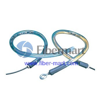
Optical fiber identifier is an essential installation and maintenance instrument which can identify the optical fiber by detecting the optical signals transmitted through the cables, during this process the fiber optic identifier do no harm or damage to the fiber cable and it also do not need opening the fiber at the splice point for identification or interrupting the service.
 
During this process the fiber optic identifier generate no harm or damage to the fiber cable and it do not need opening the fiber at the splice point for identification or interrupting the service.This optical fiber identifier detects frequency tones at 270Hz, 1KHZ, 2KHZ, when traffic is present on the fiber under test, an audible tone can be heard. In the meantime, it can identify the traffic direction that indicated by LED with illumination.
 
The fiber optic identifier is intended for engineers and technicians to identify dark or live fiber and excessive losses due to the misalignment of mechanical splices or poor connections.
 
The relative energy studying might be utilized to support inside the identification of the reside optical fiber.There are numerous medical tests that might be done to isolate the preferred soluble fiber cable television from the party of fibers not having getting straight down the link(s). 3 procedures that could possibly be utilized consist of comparing relative power, inducing macrobends, and different the optical energy within the source. No solitary technique is most excellent or necessarily definitive. making use of a single or even a mixture of those procedures might be required to isolate the fiber.

Wednesday 29 August 2018

Pulling eye 50M Multimode 12 Fiber LC/FC/SC/ST Pre-terminated Fiber Cable


FM SKU#:SKU30227T
MFG PART#:

50M Multimode 12 Fiber LC/FC/SC/ST pre-terminated Fiber cable

Fiber-Mart's Pre-Terminated cables can be manufactured to suit your individual project requirements. Our fully tested Pre-Terminated fiber optic cables can be supplied to your specific length, core count, colour and connector type and is an ideal solution for installers without fiber optic experience quoting for projects involving fibre cablin.Fiber Optic Pre-terminated cable assembly, with connectors on both ends or only one end.The connectors options: LC, SC, ST, FC, MTRJ, MTP, E-2000.

This price on the website is for 50M length,please feel free to enquiry us for the other length standard


Specifications

  • Lower installation cost
  • Lower cost of ownership
  • No consumables, termination tool kits or specialized termination training required
  • No cable preparation necessary.
  • No installer termination errors.
  • Cables arrive ready for installation and are available with factory installed pulling eyes.
  • Fully tested, labeled and documented
  • Higher performing factory terminated connectors provide improved end-to-end attenuation, throughput and application migration.
  • Improved link loss budgets.
  • No cable or connector scrap.

Characteristics

  • Custom length
  • Indoor and outdoor available
  • PVC/LSZH outer Jacket

Applications

  • Enterprise Premise and campus applications
  • Data centre: Trunk cables to equipment distribution area and storage network

Sample Picture


Mechanical Drawing

12 Fibers Custom Indoor/Outdoor Single mode PreTerminated Assembly

Reduce installation time with Pre-Terminated Fiber Patch Cables and the controlled factory processes with pre-termination results in superior performance. Consistent, high quality connector end-face geometry results in lower insertion loss and better end-to-end attenuation in the system. The "Pulling Eye" structure plays a critical role in the cable assembly connection. It allows strain relieved and provides excellent protection to connectors. These pre-engineered, factory-terminated and tested trunk cables connect central patch locations to zones or "pods".


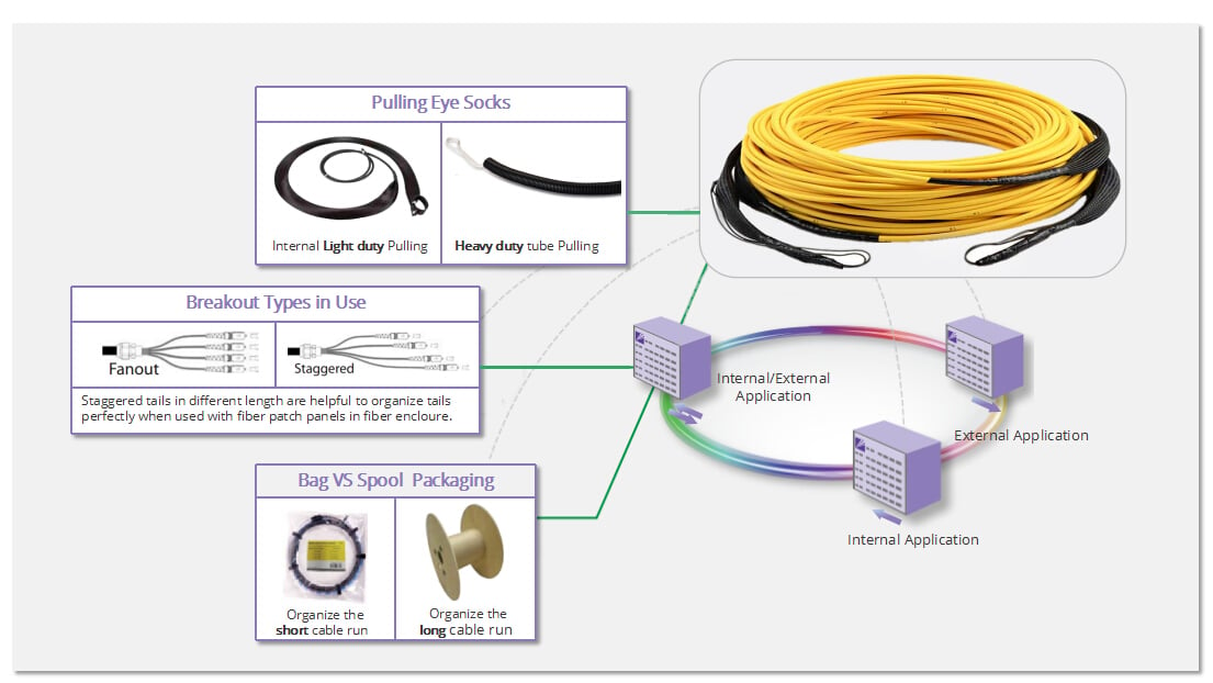
"Pulling Eye" and "Packaging Details" of Pre-terminated Cable Assembly
A pulling eye is recommended in this pre-terminated cable assembly. With this useful structure, hassle-free installation and erro-free performance will be no problem. In some cases, you may need to order the cable with two pulling eyes to pull from an intermediate point rather than from point to point. Besides, we offer excellent packaging methods, such as wooden spool, plastic spool or box according to the cable length, which are easy to move and organize the cable.


Key Features


Factory terminated and tested2.0mm default, 0.9mm 3.0mm of breakout OD can be customizedPVC jacket default, LSZH and other premium material availableHigh density and faster cable connectivity
2, 4, 6, 8, 12, 24 cores and customized is availableLC, SC, FC, ST connectors with UPC/APC polishing type availableHassle-free installation and erro-free performanceExcellent wooden, plastic and paper spool packaging


How to Install and Use the "Pulling Eye"
Pulling eye installation is simple and less tools used. The picture below can illustrate well the installation step. As for the specific situation of assembly, if the assembly is installed inside closed ducting - protection of tails and pulling system may need to be applied. Please consider installation method selecting target design. Some multifibre assemblies features the pulling system applied as a standard whereas for some designs it will be optional.


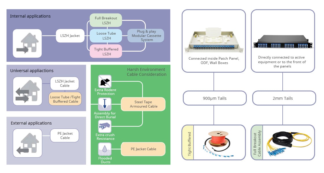
Where Will The Assembly Be Installed And Connected
For different application environment, Fiber-MART provides Internal, External, Universal pre-terminated patch cable types which are of premium characteristics and high performances. The network topology can be reduced and simplified by direct connection to active equipment bypassing wall boxes, ODFs of fiber patch panels, the end result is a greatly improved power budget and reduced fiber management space. For more information, please contact our sales.


Product Guidance

2 Fibers WallMounted Military Field Connector to LC/SC/ST/FC Fiber Optic Patch Cable


Features
Moulded plastic compound body, for long useCross the panel with seal design, simultaneous connector 2 to 6 fibersNeutral mechanism, connector and receptacle random linkingCeramic ferrule and sleeve: PC,UPC polishingCable length: 1MFiber number: 2 fiberConnector: wall-mount military field cptic cable connector to LC/SC/ST/FC
Applications
Optical fiber military communication networksMilitary computer networksVehicle-borne, air-borne or carrier-borne equipments
Specifications

ItemParameter
Fiber typeSinglemodeMultimode
2 fibers4 fibers6 fibers2 fibers4 fibers6 fibers
Insert loss≤0.6≤0.8≤1≤0.6≤0.8≤1
Repeatability≤0.2≤0.2≤0.2≤0.2≤0.2≤0.2
Vibration10Hz 500Hz,98m/s2
Shock490m/s2
Durability(per time)1000cycles
Working temperature-40  up to +85
Temperature cycle-40  up to +85 , three cycles
Fibers2 fibers4 fibers6 fibers
Cable Crush Resist1200N(long-term) 1400N(long-term)600N(long-term)  800N(short-term)
Cable Outer Diameter5.0mm6.5mm6.5mm

FIBER PATCH CABLES AND THEIR USES

by www.fiber-mart.com
Fiber patch cables are the backbone of the fiber optics industry. These fiber patch cables are strands of optically pure glass as thin as human hair.
 
These cables carry information via mode of transmission of light. Short patch leads usually made with stranded wire are flexible patch cables. The fiber patch cables are used to plug one piece of equipment into another. To sum, these cables are the most opted solution these days for the networking and broadcasting industry.
 
They have various uses in all kinds of industries. Fiber patch cables are used in:
 
Medical imaging
Mechanical engineering
LAN applications
Cable TV networks
Telephone lines,
and More!
Fiber patch cables have revolutionized the total network industry of telephones, cable, internet, audio applications, etc. The fiber patch cables offer accurate signal transfer which is totally distortion free. Thus due to these cables the audio or video transmission is completely distortion free and crystal clear. Since these fiber patch cables use light as a mode of transmission there is no hazard of electric interferences or any tampering.
 
Fiber Patch Cables Used for? 
 
Fiber patch cables are used to two nearby components with fiber connectors. Fiber patch cables come with their respective connectors. They can be an ideal and easy replacement of copper cables because they use the same RJ45 connector as copper patch cables.
 
What are Fiber Patch Cables Available in? 
 
Fiber patch cables are available in simplex, duplex, multimode, single mode with STST, STSC, SCSC connectors. Fiber patch cables are of two prominent types – single mode and multimode. Single mode fiber patch cables are used in long-distance high capacity voice applications like telephone transmission or long distance gigabit networking. These fiber patch cables can use 9/125 micron bulk fiber cables and connectors at both ends.
 
Multimode fiber patch cables are used in computer industry which is standard for data applications like local area network, wide area network, etc. Fiber patch cables in multimode are available in 50µm and 62.5µm. SC, ST, LC, FC, MT-RJ, E2000 and MU connectors have polished ceramic ferrules for precision and durability. The SC and LC duplex fiber patch cables come equipped with a clip to maintain polarity.
 
ST to ST fiber patch cable gives unlimited bandwidth at high speeds over long distances. These fiber patch cables are ideal for connections between fiber patch panels, hubs, switches, media converters and routers, etc. Fiber patch cables provide higher speeds and increased bandwidth, compared to conventional twisted-pair copper cable. These fiber patch cables are compatible with all standard fiber optic equipment and connectors. Ceramic connectors of these fiber patch cables ensure low signal loss and high reliability along with total immunity to electrical and electromagnetic interference.

How To Make Fiber Optic Patch Cables

by www.fiber-mart.com
Times are tough these days, which is why many people are looking to save a few dollars any way they can. A couple weeks ago we made a video showing you How To Build an Inexpensive Wall Mount Fiber Box. We've already had quite a few customers thank us for that cost saving solution. Today, let's talk about making your own fiber optic patch cables.
 
Seems like just about everyone in the low voltage industry has made their own ethernet cat5e/cat6 cables at least once in their life (me included). And I'm sure you have too. So you're thinking, those are really easy and only take a few minutes, why don't I just start making my own fiber cables. Unfortunately, we're not comparing apples to apples here. Making your own fiber cables CAN be an easy process, but it's not very economical. I'm talking about the FAST fiber connectors from AFL Telecommunications. Although these connectors require only a couple minutes per strand to complete, they are much pricier than regular connectors and still require a couple expensive tools. It wouldn't make sense to buy these unless you already had the tools and did fiber terminations regularly. Even then, the cost of the connectors make this an expensive way to make fiber jumpers. If this is still something your interested in, watch the video below.
 
The other option for making fiber cables would be epoxy fiber connectors. These connectors have been around for quite a while now and are fairly inexpensive. The problem with these connectors is the amount of time involved in terminating them. In addition, you still need all the tools and testing equipment to get the job done. Well, I thought you were going to show us how to make fiber jumpers? That's where the "kinda" comes in. Watch the video below for a brief explanation on making fiber cables, but when it comes down to it, buying pre-made fiber cables is the way to go. You can order them in any length you need, with any type of fiber, and any type of connector. If you need more than 2 strands of fiber, or plan on using them for a long distance, I would recommend Pre-Terminated Fiber Optic Cable. Pre Terminated fiber assemblies are just like the fiber jumpers, but can be pulled long distances and are much more durable. To order any of the products talked about in this article, simply click the links above or visit www.fiber-mart.com.

PICK THE RIGHT PATCH CORD FOR YOUR FIBER OPTIC NETWORK

by www.fiber-mart.com
Choosing your fiber jumpers is no easy task. The fiber optic jumper cable you pick can affect how quickly data is transmitted from point to point.
 
A fiber jumper—more commonly called a fiber patch cord—is a length of fiber cable that connects end devices or network hardware to your structured cabling system. The cable is terminated with LC, SC, MTRJ or ST connectors at each end.
 
Jumpers come in simplex or duplex and should be chosen based on your network needs. Figuring that part out is as easy as knowing the difference between its and it's when you're writing blog posts.
 
SIMPLEX VS DUPLEX JUMPERS
Simplex cables, a single strand of glass encased in plastic, are generally used when a data transmission needs to travel in only one direction. They're a great choice for connections within buildings or across large areas like cable TV networks.
 
Duplex cables, two strands of fiber in a single cable, are like a two-lane highway. The signal needs to go both ways, called bi-directional communication, between your active gear.
 
One cable is transmitting the signal, while the other is receiving it. Duplex cables are typically used in larger work stations, switches, servers and on major networking hardware.
 
Duplex cables also come in zipcord or uniboot construction. In zipcord, two fiber strands are fused together but are easily torn apart when it's time to mine out either the transmission or receiver strand.
 
For uniboot, the two fibers merge into a single connector at either end, making replacement and maintenance a bit more difficult and costly than zipcord cables.
 
CHOOSING YOUR PATCH CORD
Single-mode simplex fiber carries only one ray of light at a time. It's extremely reliable and holds a high-carrying capacity for long-distance transmissions.
 
Since it requires less material, it's usually more cost-effective than duplex cable. It's the most commonly used cable in modern communications, because of its high capacity, allowing for higher transmission speeds and more bandwidth.
 
The risk you run is the amount of fiber you're going to have on your fiber distribution frames.
 
 
Duplex jumpers help keep your data center cleaner and tidier. They allow you to require less cable, and maintenance becomes a lot easier.
 
The choice between simplex and duplex jumpers really depends on your network—who it's serving and how complex it needs to be.

Tuesday 28 August 2018

20x 40GbE QSFP+ with 4x 100GbE QSFP28 Switch S805020Q4C

20x 40GbE QSFP+ with 4x 100GbE QSFP28 Switch S805020Q4C

The S8050-20Q4C reference design, the high-density 10G/40GE platform with native 100GE (4x25G SerDes) uplinks, supports multiple form factors and includes fiber-mart Open Switch Platform (OSP) reference software for Data Center/SDN/Openflow and enterprise applications.

S8050-20Q4C reference design provides a comprehensive solution for data center Spine/Leaf switches with highlighted network visibility features. It is also the first Terabit platform with carrier domain features like OAM and PTP enabled. The reference design is equipped with an advanced SDK package with productized CLI for customer to do SDK-level configuration and verification.

Switch ClassLayer2/3, Dater center, MetroNon-blocking Throughput1.2Tbps
40-Gigabit QSFP+20Switching Capacity2.4Tbps
100-Gigabit QSFP284CPUFreescale PowerPC P1010
Typical/Max Power Draw120W/160WSystem Memory2 GB
100/1000 Mgmt Ports1Flash Storage Memory2 GB
RS-232 Serial Ports1 (RJ-45)Packet Buffer Memory9 MB
USB Ports1Max VLANs4094
Packets/Second1200MppsMax MAC Entries128K
Jumbo Frames9600 BytesEnclosure TypeRack-mountable 1U
Hot-swap Power Supplies2(1+1 redundancy)Dimensions (H x W x D)43.6x440x470 mm
Hot-swappable Fans4(N+1 redundancy)Weight(With one PSU)8.3kg

Product Highlights


  • 20 QSFP+ Ports
    20x40GBASE QSFP+ Ethernet Ports.
  • 4 QSFP28 Ports
    4x100GBASE QSFP28 Ethernet Ports.
  • Multi-Node Redundancy
    Dual power modules and Four fans for uninterrupted performance assurance.


Model Comparison


48x Gigabit SFP with 4x 10GbE SFP+ Switch S580048F4S

48x Gigabit SFP with 4x 10GbE SFP+ Switch S580048F4S

48xGigabit SFP with 4x10GbE SFP+ Switch S5800-48F4S


S5800-48F4S is high performance Ethernet switch to meet next generation Metro, Data Center and Enterprise Ethernet network requirements designed based on high-end scalable chipset with integration of Layer 2 to Layer 4 packet processing engine, traffic management and fabric interface.

S5800-48F4S is cost-effective Ethernet access and aggregation platform to Metro, Enterprise and Data Center application. It provides high port density with 48GE fixed port and adopts flexible modular design to support maximum 4x10G uplinks.

Switch ClassLayer2/3Non-blocking Throughput88Gbps
1-Gigabit SFP48Switching Capacity176Gbps
10-Gigabit SFP+4CPUCavium CN5010-500BG564-CP-G/500MHz
Typical/Max Power Draw75W/85WMax VLANs4K
100/1000 Mgmt Ports1Forwarding Rate132 Mpps
RS-232 Serial Ports1 (RJ-45)Flash Storage Memory32MB
USB Ports1Enclosure TypeRack-mountable 1U
Hot-swap Power Supplies2(1+1 redundancy)Dimensions (H x W x D)43.6x440x 400 mm
Hot-swappable Fans4(N+1 redundancy)Weight(With one PSU)6.3kg

Product Highlights


  • 48 SFP Ports
    48x100/1000 Base-X SFP Ethernet Ports.
  • 4 SFP+ Ports
    One 4x10GE SFP+ Card support up to 4 10G SFP+ transceivers.
  • Multi-Node Redundancy
    Dual power modules and Four fans for uninterrupted performance assurance.


Model Comparison


ImagePart NumberID#DescriptionPrice 
1G SFP Transceivers
SFP-GB-GE-T200571000BASE-T SFP Copper RJ-45 100m TransceiverUS$  16.00Add to Cart
SFP1G-SX-85298381000BASE-SX SFP 850nm 550m DOM TransceiverUS$  6.00Add to Cart
SFP1G-SX-31298481000BASE-SX SFP 1310nm 2km DOM TransceiverUS$  11.00Add to Cart
SFP1G-LX-31298491000BASE-LX/LH SFP 1310nm 10km DOM TransceiverUS$  7.00Add to Cart
SFP1G-EX-55298541000BASE-EX SFP 1550nm 40km DOM TransceiverUS$  24.00Add to Cart
SFP1G-ZX-55298561000BASE-ZX SFP 1550nm 80km DOM TransceiverUS$  24.00Add to Cart
10G SFP+ Transceivers
SFP-10GSR-855877310GBASE-SR SFP+ 850nm 300m DOM IND TransceiverUS$  16.00Add to Cart
SFP-10GLRM-311159010GBASE-LRM SFP+ 1310nm 220m DOM TransceiverUS$  34.00Add to Cart
SFP-10GLR-315877410GBASE-LR SFP+ 1310nm 10km DOM IND TransceiverUS$  34.00Add to Cart
SFP-10GER-551159210GBASE-ER SFP+ 1550nm 40km DOM TransceiverUS$  180.00Add to Cart
SFP-10GZR-551159510GBASE-ZR SFP+ 1550nm 80km DOM TransceiverUS$  400.00Add to Cart
SFP-10GZRC-552979910G SFP+ 1550nm 100km DOM TransceiverUS$  500.00Add to Cart

Are You Familiar With Optical Switch?

by www.fiber-mart.com
There are lots of fiber optical devices used for communication networks. And optical switch is the one transmitting light signals between different channels. If a light signal is propagated from one phone or computer to another, it may be required to move between different fiber paths. Under this condition, optical switch plays an important part as it can transfer the signal with a minimum loss of voice or data quality. With the growth of technologies, many new methods have been combined with optical switch to achieve higher speed performance. Today, let’s step into the world of optical switch and explore its secrets.
 
Types of Optical Switches
Basically, there are two types of optical switches – OEO (optical-electrical-optical) switch and OOO (optical-optical-optical) switch. Network management functions of operating a network are available today using an optical switch with an electronic-based switching matrix. OEO switch receives the optical signal and converts it into electrical signal. Then it switches the signal into a different port and converts it back to optical signal for the network. By using an electronic fabric, OEO switch accomplishes bandwidth grooming and overcomes the network impairments.
 
 
OOO switch or all-optical switch enables the managing and switching of optical signals without converting them into electronic signals. This is especially attractive to those carriers operating large offices where up to 80 percent of the traffic is expected to pass through the office on its way to locations around the globe. It receives the optical signal and switches it to a different port in the optical domain, then returns it back to the network as an optical signal.
 
Technologies Applied In Optical Switch
 
MEMS (micro electrical mechanical system) technology uses many moving mirrors to switch the signals by deflecting light waves from one port to another. There are two MEMS structures. One is called 2D MEMS mirror, and another is 3D MEMS mirror. 3D MEMS based optical switch is more widely used in the industry. Following figure shows the operation process of the MEMS switching.
 
 
Liquid Crystal Switching
Liquid crystal technology employs the polarization effects of light in liquid crystals for light switching. At first, the light is filtered through polarization beam splitter to be separated into two or more paths. Then the light is put through a liquid crystal where its polarization property may be changed. At last, the light comes into the polarization beam combiner to be steered into the output port. And the output port is decided by the new polarization property of light.
 
Bubble Based Switching
Bubble based switch can use air bubbles and micro trenches aligned vertically and horizontally to switch the light. When there is no need for switching, the light can pass through the trenches uninterrupted. This technology has the benefits of low cost and fast switching time.
 
Thermo-Optic Switching
Thermo-optic switch will send light down a wave guard. The light is then split into different wave guards. If a switching command is issued, one of the wave guard arms is heated and the light within the wave guard will change its optical path length. Then the light is recombined and the path lengths of the lights are measured. If the lengths are different then the beam will be switched into one output port. If they are the same, the beam will be switched into another port.
 
 
Applications
Optical switches can be applied to various applications. In high speed networks, switches for this function are usually used within optical cross-connects to handle large amount of traffic. Another application is for the protection switching. If a fiber fails, the switch allows the signal to be rerouted to another fiber before the problem occurs. Also, the OADM (optical add-drop multiplexer) will use some optical switches to convert signals from a DWDM stream allowing carriers to selectively remove some wavelengths from a signal.
 
Conclusion
Optical switch is an important device that transfers light signals into different channels. Based on the original OOO type and OEO type optical switches, many new technologies have been brought in, which ensures the high performance of optical switches. With growing demands for higher data bandwidth, the future of optical switch is bright.

How to Understand PoE and PoE+ Switches

by www.fiber-mart.com Power-over-Ethernet (PoE) is the technology that allows network switches to transmit power and data through an Ethe...