Thursday 27 September 2018

Armored Cable vs. Flexible Cable: Key Differences

by www.fiber-mart.com
When transmitting data or conducting power in harsh environments, protecting your cables is crucial to safe and reliable operation. This is where armored cables come into play. They are used primarily in industrial applications, often in cable trays and raceways. They often not used in flexing applications. While they could operate there, the connector cable would create a weak link. To combat this, you should use either a high-flex cable on the inside or discreet wires.
Jacketing materials—such as a silicone tube-covered, thermoplastic elastomer or PVC—further protect the cables from harsh chemicals, oils and sunlight, but also prevent physical failure by repetitive impacts, abrasion with loaded components, and weld slag. In addition, most armored cable jacketing materials are flame resistant.Armored cables feature some type of metal sheath that is the first layer of armor. It is usually made of interlocking or continuous aluminum or stainless steel, or it can be covered in a smooth or corrugated metal tape. According to Mencom, which uses a stainless-steel design, the armor protects the cable inside from water damage by high-pressure washdown, cleaning agents and extreme temperatures.
Unlike cable shielding, which is often braided or a foil wrap design, the armor shield is wound around the cable, giving it a corded, corrugated appearance.
Two gentleman named Edwin Greenfield and Gus Johnson first developed armored cable, or BX cable, in the early 20th century. It used a flexible steel cover, but now more commonly uses flexible aluminum conduits. Metal-clad cables are typically galvanized steel or aluminum interlocking cable. And some companies’ armored cables, such as Mencom, use a woven flexible stainless-steel design.
A big difference in the three designs is in how they are ground. BX are usually ground through the sheath; this is why BX cables most often need to be buried. Armored cables also ground through the sheath but can be exposed at certain areas without causing the system to ground. Metal-clad armored cables, like those used in industrial settings, feature a grounding wire—usually an annealed bare copper wire—inside the wire bundle. This allows them to be used in open areas, such as in running through factories and plants throughout raceways and cable trays and carriers.
Armored cables must be IP67-rated and certified to UL and NEC standards, among others.

Use Armored Cables for all your cabling needs

by www.fiber-mart.com
Wires enclosed in a metal covering are called armored cables. Inside the flexible metal covering, are an insulated hot and neutral wires and a bare bonding wire. Armored fiber-optic cables are often placed in a network for an added automated protection. The armoring is of two types: corrugated (Steel Wire Armor) and interlocking (Aluminium Wire Armor). Corrugated armor is a coated steel tape folded around the cable longitudinally found in outdoor cables.
 
It offers an extra automated and rodent protection. Interlocking armor is an aluminum armor that is helically wrapped around the cable and found in indoor and indoor/outdoor cables. It offers virility and a strong crush resistance. A single core armored cable will always have a layer of aluminium wire armor (AWA) instead of steel wire armor (SWA) as the steel in SWA has a much lower conductivity and thus a higher resistance than aluminium.
 
If it were used in a single core cable, the magnetic field generated would induce an electric current in the armor and along with the increased resistance, would have caused a heating effect. AWA is non-magnetic in nature and therefore has a much better conductivity (lower resistance), so it can conduct these induced currents more efficiently than steel. SWA is used in multicore armored cables because the electromagnetic fields from the adjoining cores effectively cancel each other out, meaning less current is induced into the armor.
 
In the course of fiber-optic installations, there is a need to provide extra shielding for the cables due to the installation environment. The environment may be underground or inside the buildings with obstructed passages. Installing an armored fiber-optic cable in such a setting would provide an extra shielding for the optical fiber and add a security to the network, lessen the risk of downtime and cable damage due to rodents, construction work and any other external factor.
 
Though there are many benefits of installing armored fiber-optic cables but the need to bond and ground the cable is one major drawback. This drawback too can solved by using a dielectric-armored cable. One can find the armored cables everywhere and in everything ranging from transmission, power, distribution networks and the renewable energy sector to the oil, gas and petrochemical, water treatment and transport industries. Thus, the use of these cables has almost reached all the sectors equally.

Primary Features of Underground Armored Cable

by www.fiber-mart.com
What is the structure of the underground power cable?
 
Plenty of cables and wires are available for all types of electrical and cable applications. Choosing the correct one can be easy enough if you know, as a professional electrician, what application the product is for. Much of the tine armoured cables are used in mains supplies and underground sewer systems or railways.
 
There are a variety of armoured cables available including those that are made of 2 to 7 core wires. Underground armoured cable has distinct features. They are noted for the different number of conductors within them which are covered with insulation and a layer of protective PVC or other durable material. They also have bedding and a sheath. They are comprised often of Huadong steel wire armoured cable and often called SWA wires.
 
What are the advantages of underground armoured cable?
Electrical power can go through the cables underground, although there are some types that work above ground. Underground cables have the ability to endure no matter how bad the weather gets. Click here to know more about custom power cables if you need.
 
They are easy and inexpensive to maintain because they are protected underground. They also tend to fault less often than the above ground cables because there is less of a chance of voltage drops. If overhead lines cannot be installed these are the only option. They are costly to install, but they offer so many advantageous features that it ends up being a worthwhile investment. If you want to buy underground armoured cable, Huadong Cable Group is a good underground power cable factory in China.
 
They are worth the extra price because they also make it difficult for anyone to be injured when coming in contact with them. They are buried underground so this is unlikely unless there is some type of natural disaster that disrupts them when they are buried.
 
What are the performance features of underground armored cable?
Urban lines work better when they can transmit through underground cables. They can go up to 20 circuits whereas the above ground cables only go from 2 to 4 circuits.
 
These cables last a long time because they do not come into contact with water, acids or alkali like above ground wires and cables often do. This makes them a lot more reliable when used in large cities that depend on constant power.buy discount underground armoured power cable quotation
 
What these cables do for cities is keep them looking beautiful. There is less clutter when cables are buried underground. Also, land is an important resource. It can be used in several ways when cables are laid beneath the ground and beneath the buildings to which they supply power. Click here to know more about underground armored cable.
 
There was a time where buildings were strewn with cables for mains supplies. Sometimes, these are still the only option for connecting power sources to buildings. However, instead of having to choose to destroy the look of a row of buildings, underground armoured cables offer the convenience of keeping the look of a neighborhood or city neater. http://huadongswacable.com/underground-power-cable/
 
They also work well to maintain safety for people riding in underground railways. There are many advantages and features of armoured cable. They come in a variety of sizes and offer a lot of durability. They even help keep a city or other urban area looking more attractive, clean and appealing to those who live and work there.

Wednesday 26 September 2018

SM 9/125 Simplex Fiber Patch Cable FTTH Drop Cable FRP G652D PVC

FM SKU#:SKU00317L
Model#:FTTH-FM005
MFG PART#:
FTTH Drop cable is designed for last-one-mile in the fttx net-work, enhancing the accessiblility to the fibr and maximizes the instalation workability. FTTH Cable directly connected to their homes, their bandwidth, wavelength and transmission technology. Also, customers can specify your required connectors.
Note: This picture is for SC-SC SM SX FTTH Drop Cable. Please just take it as a reference.

Key Features

  • Special low-bend-sensitivity fiber provides high bandwidth and excellent communication transmission property
  • Two parallel FRP strength members ensure good performance of crush resistance to protect the fiber
  • Single steel wire or massagers as the additional strength member ensures good performance of tensile strength
  • Simple structure, light weight and high practicability
  • Novel flute design, easily strip and splice, simplify the installation and maintenance
  • Low smoke zero halogen and flame retardant sheath

Applications

  • Access network, FTTH (Fiber to the home)
  • Indoor cabling, and end users directly cabling
  • Access building cable

Specifications

ItemsParameters
Cable diameter2.0 x 3.0mm
Cable jacket materialLSZH or PVC
Cable typeSM:9/125
WavelengthSM-1310nm, 1550nm
Insertion loss(dB)≤0.3dB
Return Loss(dB)≤-50dB
Operating temperature(℃)-20 to +70
Storage Temperature(℃)-20 to +80

Duplex FTTH Indoor Cable FRP G652D PVC

Duplex FTTH Indoor Cable FRP G652D PVC


FTTH indoor cable is made up by optical communication unit, strengthen pieces and the sheath composition, that is put the optical communication unit in the centre, both sides parallel place two root non-metallic strengthen members (FRP) or metal strengthening component phosphating steel wire, finally squeeze the black color LSZH sheath into cable. Also, customers can specify your required connectors.
Note: This picture is for SC-SC SM DX FTTH Indoor Cable. Please just take it as a reference.

Key Features

  • Special low-bend-sensitivity fiber provides high bandwidth and excellent communication transmission property
  • Two parallel FRP strength members ensure good performance of crush resistance to protect the fiber
  • Simple structure, light weight and high practicability
  • Novel flute design, easily strip and splice, simplify the installation and maintenance
  • Low smoke zero halogen and flame retardant sheath

Applications

  • FTTH system
  • Indoor riser level and plenum level cable distribution
  • Interconnect between instruments, communication equipments

Specifications

ItemsParameters
Cable diameter2.0 x 3.0mm
Cable jacket materialLSZH or PVC
Cable typeSM:9/125
WavelengthSM-1310nm, 1550nm
Insertion loss(dB)≤0.3dB
Return Loss(dB)≤-50dB
Operating temperature(℃)-20 to +70
Storage Temperature(℃)-20 to +80

Loose-Tube and Tight-Buffer Cable Application of FTTH

by www.fiber-mart.com
FTTH makes use of Fiber Optic technology to enhance communication for households. FTTH stands for Fiber to the Home, and many experts believe that FTTH cable will soon replace the traditional copper cables. There are various other elements of FTTH. FTTH Flat Drop Cable is generally also known as indoor cable. Other elements of the technology include instrumentation cables and cable glands. Next let us make a brief introduction of cable construction and the difference of Loose-Tube and Tight-Buffer Cable.
 
Optical-Cable Construction
 
The core is the highly refractive central region of an optical fiber through which light is transmitted. The standard telecommunications core diameter in use with SMF is between 8  m and 10m, whereas the standard core diameter in use with MMF is between 50m and 62.5m. The diameter of the cladding surrounding each of these cores is125m. Core sizes of 85m and 100 m were used in early applications, but are not typically used today. The core and cladding are manufactured together as a single solid component of glass with slightly different compositions and refractive indices. The third section of an optical fiber is the outer protective coating known as the coating. The coating is typically an ultraviolet (UV) light-cured acrylate applied during the manufacturing process to provide physical and environmental protection for the fiber. The buffer coating could also be constructed out of one or more layers of polymer, nonporous hard elastomers or high-performance PVC materials. The coating does not have any optical properties that might affect the propagation of light within the Breakout Fiber Optic Cable. During the installation process, this coating is stripped away from the cladding to allow proper termination to an optical transmission system. The coating size can vary, but the standard sizes are 250m and 900m. The 250- m coating takes less space in larger outdoor cables. The 900- m coating is larger and more suitable for smaller indoor cables.
 
 
Three types of material make up fiber-optic cables:
 
Glass
 
Plastic
 
Plastic-clad silica (PCS)
 
These three cable types differ with respect to attenuation. Attenuation is principally caused by two physical effects: absorption and scattering. Absorption removes signal energy in the interaction between the propagating light (photons) and molecules in the core. Scattering redirects light out of the core to the cladding. When attenuation for a fiber-optic cable is dealt with quantitatively, it is referenced for operation at a particular optical wavelength, a window, where it is minimized. The most common peak wavelengths are 780 nm, 850 nm, 1310 nm, 1550 nm, and 1625 nm. The 850-nm region is referred to as the first window (as it was used initially because it supported the original LED and detector technology). The 1310-nm region is referred to as the second window, and the 1550-nm region is referred to as the third window.
 
Glass Fiber-Optic Cable
 
Glass fiber-optic cable has the lowest attenuation. A pure-glass, fiber-optic cable has a glass core and a glass cladding. This cable type has, by far, the most widespread use. It has been the most popular with link installers, and it is the type of cable with which installers have the most experience. The glass used in a fiber-optic cable is ultra-pure, ultra-transparent, silicon dioxide, or fused quartz. During the glass fiber-optic cable fabrication process, impurities are purposely added to the pure glass to obtain the desired indices of refraction needed to guide light. Germanium, titanium, or phosphorous is added to increase the index of refraction. Boron or fluorine is added to decrease the index of refraction. Other impurities might somehow remain in the glass cable after fabrication. These residual impurities can increase the attenuation by either scattering or absorbing light.
 
Plastic Fiber-Optic Cable
 
Plastic fiber-optic cable has the highest attenuation among the three types of cable. Plastic fiber-optic cable has a plastic core and cladding. This fiber-optic cable is quite thick. Typical dimensions are 480/500, 735/750, and 980/1000. The core generally consists of polymethylmethacrylate (PMMA) coated with a fluoropolymer. Plastic Fiber Optic cable was pioneered principally for use in the automotive industry. The higher attenuation relative to glass might not be a serious obstacle with the short cable runs often required in premise data networks. The cost advantage of plastic fiber-optic cable is of interest to network architects when they are faced with budget decisions. Plastic fiber-optic cable does have a problem with flammability. Because of this, it might not be appropriate for certain environments and care has to be taken when it is run through a plenum. Otherwise, plastic fiber is considered extremely rugged with a tight bend radius and the capability to withstand abuse.
 
Plastic-Clad Silica (PCS) Fiber-Optic Cable
 
The attenuation of PCS fiber-optic cable falls between that of glass and plastic. PCS Fiber Optic Cable has a glass core, which is often vitreous silica, and the cladding is plastic, usually a silicone elastomer with a lower refractive index. PCS fabricated with a silicone elastomer cladding suffers from three major defects. First, it has considerable plasticity, which makes connector application difficult. Second, adhesive bonding is not possible. And third, it is practically insoluble in organic solvents. These three factors keep this type of fiber-optic cable from being particularly popular with link installers. However, some improvements have been made in recent years.
 
 
FTTH (Fiber to the Home) network compared with technologies now used in most places increases the connection speeds available for residences, apartment building and enterprises. FTTH network is the installation and use of optical fiber from a central point known as an access node to individual buildings. The links between subscriber and access node are achieved by fiber jumper cables. Loose-tube and tight buffer cables are commonly used to transmit signals with high speed, which are capable of supporting outdoor or indoor environment. Is there a cost-effective solution that can support both indoor and outdoor environment in FTTH network? To answer this, the construction and comparison of loose tube cable and tight buffer cable will be introduced in the following article.
 
Loose-Tube and Tight-Buffer Cable
 
The “buffer” in tight buffer cable refers to a basic component of fiber optic cable, which is the first layer used to define the type of cable construction. Typically a fiber optic cable consists of the optical fiber, buffer, strength members and an outer protective jacket (as showed in Figure 1). Loose-tube and tight-buffer cables are two basic cable design. Loose-tube cable is used in the majority of outside-plant installations, and tight-buffered cable, primarily used inside buildings.
 
Loose-tube and tight-buffer cables
 
Loose-tube cable consists of a buffer layer that has an inner diameter much larger than the diameter of the fiber see in the following picture. Thus, the cable will be subject to temperature extremes in the identification and administration of fibers in the system. That’s why Loose Tube CST Fibre Cable are usually used in outdoor application. The loose-tube cables designed for FTTH outdoor application are usually loose-tube gel-filled cables (LTGF cable). This type of cable is filled with a gel that displaces or blocks water and prevents it from penetrating or getting into the cable.Tight buffer cable using a buffer attached to the fiber coating is generally smaller in diameter than loose buffer cable (showed in Figure 2). The minimum bend radius of a tight buffer cable is typically smaller than a comparable loose buffer cable. Thus tight buffer cable is usually used in indoor application.
 
loose buffer cable
 
Tight buffered indoor/outdoor cable with properly designed and manufactured can meet both indoor and outdoor application requirements. It combines the design requirements of traditional indoor cable and adds moisture protection and sunlight-resistant function to meet the standards for outdoor use. Tight buffered indoor/outdoor cable also meets one or more of the code requirements for flame-spread resistance and smoke generation.
 
 
In short, FTTH cable is transforming the way we communicated in the past; and it will soon become the norm. FTTH network can be increased reoffers high quality fiber cable assemblies such as Patch Cords, Pigtails, MCPs, and Breakout Cables etc. All of our custom fiber patch cords can be ordered as Single Mode 9/125, Multimode 62.5/125 OM1, and Multimode 50/125 OM2 and Multimode 10 Gig 50/125 OM3/OM4 fibers. If you have any requirement, please send your request to us.

PLC Splitter Applications in FTTH Network

by www.fiber-mart.com
TTH mainly uses PON network technology, which requires a large number of low-cost optical splitters and other optical passive. Optical splitter device is an integral part of FTTH and with the promotion of FTTH, there would be a great market demand. The traditional preparation of optical splitter technology is fiber fused biconical taper (FBT) technology. Its characteristics are mature and simple technology. The disadvantage is that the assigned ones too large, and the device size is too large, which caused the decrease in yield and the rising cost of single channel, shunt reactive stars uniformity will deteriorate. FBT technology based fiber optic splitter preparation techniques have been unable to adapt to the market demand.
 
 
PLC splitter or planar lightwave circuit splitter is a passive component that has the special waveguide made of planar silica, quartz or other materials. It is employed to split a strand of optical signal into two or more strands. PLC splitter also has lots of split ratios, and the most common ones are 1:8, 1:16, 1:32, 1:64, 2:8, 2:16, 2:32 and 2:64. There are many types of PLC splitters to meet with different needs in OLT and ONT connection and splitting of optical signals over FTTH passive optical networks. There are seven major package types of PLC splitters according to different applications, i.e. bare fiber splitter, module splitter, rack-mount splitter, Mini Type splitter, Tray splitter and LGX splitter.
 
Bare fiber optical splitter
ABS splitters
Mini Type fiber splitter
Tray splitter
Rack-mount splitter
LGX splitters
PLC splitter in mini plug-in type
 
Applications
 
Bare Fiber PLC Splitter
 
Bare fiber PLC splitter has no connector at the bare fiber ends. It can be spliced with other optical fibers in the pigtail cassette, test instrument and WDM system, which minimizes the space occupation. It is commonly used for FTTH, PON, LAN, CATV, test equipment and other applications.
 
Mini Type PLC Splitter
 
Mini Type PLC Splitter has a similar appearance as bare PLC splitter. But it has a more compact stainless tube package which provides stronger fiber protection, and its fiber ends are all terminated with fiber optic connectors. Connectors are commonly available with SC, LC, FC and ST types. Thus, there is no need for fiber splicing during installation. Mini PLC splitter is mainly used for different connections over distribution boxes or network cabinets.
 
ABS BOX TYPE PLC Splitter
 
ABS Box PLC Splitter has a plastic ABS box to protect the PLC splitter to adapt to different installation environments and requirements. Common splitter modules are 1×4, 1×8, 1×16, 1×32, 1×64, 2×4, 2×8, 2×16, 2×32. It is widely used with outdoor fiber distribution box for PON, FTTH, FTTX, PON, GOPN networks.
 
Tray Type PLC Splitter
 
Tray type PLC splitter can be regarded the fiber Tray which contains PLC fiber splitter inside a tray. It is often directly installed in optical fiber distribution box or optical distribution frame. FC, SC, ST & LC connectors are selective for termination. Tray type PLC splitter is an ideal solution for splitting at the places that are near OLT or ONU.


Tray type PLC splitter
 
 
Rack-mount PLC Splitter
 
Rack-mount PLC Splitter can be used for both indoor and outdoor applications in FTTx projects, CATV or data communication centers. It uses the 19-inch rack unit standard to contain the PLC splitter inside a rack unit.
 
LGX PLC Splitter
 
LGX PLC splitter or LGX box PLC splitter has a strong metal box to house the PLC splitters. It can be used alone or be easily installed in standard fiber patch panel or fiber enclosure. The standard LGX mental box housing provides a plug-and-play method for integration in the network, which eliminates any risk during installation. No filed splicing or skilled personnel is required during deployment.
 
Mini Plug-in Type PLC Splitter
 
Mini plug-in PLC type splitter is its small version with a compact design. It is usually installed in the wall mount FTTH box for fiber optic signal distribution.
 
Above these types of PLC splitters are typically installed to serve for PON and FTTH networks. 1xN and 2xN are the common splitter for specific applications. You can choose the correct one according to you projects and if any more questions pls feel free to contact us for any technical problem.
 

How to Reduce the Cost of FTTH Architecture

by www.fiber-mart.com
In our digital world, people increasingly require higher bandwidth to facilitate daily life, whether for leisure, work, education or keeping in contact with friends and family. The presence and speed of internet are regarded as the key factor that subscribers would take into account when buying a new house. Recently there are a growing number of independent companies offering full fiber to the home (FTTH) services, ranging from local cooperatives and community groups to new operators. Today’s article will pay special attention to the reasons why we should implement FTTH network and the methods to reduce the cost of FTTH network.
 
Why Should We Deploy FTTH Network?
 
No denying that the world is changing rapidly and becoming increasingly digital. People nowadays are knowledgeable workers who rely on fast connections to information stored in the cloud to do their jobs. Therefore, installing superfast FTTH broadband is an investment in equipping communities with the infrastructure they need to not just adapt to the present life, but to thrive in the future.
 
What’s more, the economic benefits of FTTH, for residents, businesses and the wider community are potentially enormous. While there are upfront costs in FTTH deployments, particularly around the last drop, equipment and methodologies are evolving to reduce these significantly. Fiber to the home is proven to increase customer satisfaction, and enables operators to offer new services, such as video on demand, 4K TV and smart home connectivity.
 
As well as bringing in economic benefits, FTTH broadband provides local businesses with the ability to expand, invest and seek new opportunities by providing rapid connections to major markets. All of this leads to increased investment in the rural economy, providing residents with more choice and stimulating growth.
 
What to Do?
 
Although deploying FTTH network might be similar cost as deploying copper network, there are some methods that you should know about reducing the costs of FTTH architecture. Adopting the following three principles helps achieve FTTH deployment, maximizing return on investment and dramatically reducing deployment times.
 
1. Reuse the Existing Equipment
 
Time and the total cost of FTTH deployment are typically relevant with the civil engineering side of the project, such as digging a new trench and burying a new duct within it. Where possible, crews should look to reuse existing infrastructure—often there are ducts or routes already in place that can be used for FTTH and in building deployments. These could be carrying other telecommunication cables, power lines, or gas/water/sewerage. Installing within these routes requires careful planning and use of cables and ducts that are small enough to fit through potentially crowded pathways. Figure 2 shows a generic point-multipoint architecture that fiber jumper plays an important part in it.
 
FTTH architecture
 
Additionally utilizing the push and pull cables in FTTH infrastructure simply reduce costs and install time as network installers can easily complete FTTH deployment by using pushing or pulling cables: pushing can be aided by simple, cost-effective handheld blowing machines, or pulled through the duct using a pre-attached pull cord. Even for more complex and longer environment, FTTH deployment can be quickly completed other than requiring expensive blowing equipment to propel the cable through duct.
 
2. Choose the Right Construction Techniques
 
If it is time to start digging, always make sure you use appropriate construction methods. The appropriate method will minimize cost and time by making construction work as fast and concentrated as possible, avoiding major disruption to customers or the local area. And remember to make sure you follow best practice and use the right fiber cable and duct that can fit into tight spaces and withstand the high temperatures of the sealant used to make roadways good.
 
 
The cable and duct used within FTTH implementations is crucial. Ensure that it meets the specific needs of deployments, and is tough, reliable and has a bend radius. It should be lightweight to aid installation and small enough to fit into small gaps and spaces in ducts. Also look to speed up installations with pre-connectorized cables that avoid the need to field fit or splice.
 
3. Minimize the Skills Required
 
Staff costs are one of the biggest elements of the implementation budget. Additionally, there are shortages of many fiber skills, such as splicing, which can delay the rate at which rollouts are completed. Operators, therefore, need to look at deskilling installations where possible, while increasing productivity and ensuring reliability. Using pre-connectorized fiber is central to this—it doesn’t require splicing and is proven to reduce the skill levels needed within implementations.
 
Conclusion
 
To cope with the digital world, the network is in constant need of enhancements and the increasingly stressed bandwidth and performance requires ongoing adjustment. Regardless of the FTTH architecture and the technology to the curb, the pressure is on for the network installer to deploy FTTH quickly and cost-effectively, while still ensuring a high quality, reliable installation that causes minimal disruption to customers and the local area. Fiberstore offers a variety of optical equipment that are suitable in telecom field. Our fiber optic cables are available in different optical connector, single-mode and multimode fiber as well as indoor or outdoor cables. For example, patch cord LC-LC are also provided.

Monday 24 September 2018

144 Ports 10G OM3 12-fibers MPO/MTP Ultra High Density 1U Rack

FM SKU#:SKU00138R1
Model#:HDOM3-12MTP/MPO
MFG PART#:

Description

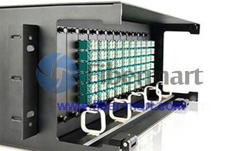
The Fiber-Mart's Ultra High Density iU Rack is specially designed to accommodate high density cabling in high end Data Centre and Telecommunication central office environment.Front and rear cable management facilitates provides a neat and tidy solution for managing incoming and exiting cables.
This rack mountable MTP cassette is loaded with 72 multimode LC 10G duplex connectors, giving it 144 ports total within 1U of rack space! Inside the MTP cassette, the fiber is spliced out up to twelve MTP connectors, giving you an easy plug-and-play option for your high-density fiber application. This high-density MTP cassette is constructed of light weight, yet durable, rolled steel.

Features

  • Fully Loaded-144 Fiber LC Ports in 1U
  • Angled Front Panel for Optimal Cable Routing
  • Removable Top for Easier Fiber Cable Management
  • Easily Accessible MTP/MPO Ports for Connection to Trunk Cable
  • Compliant IEC-61754-7, EIA/TIA-604-5 & RoHS
  • MPO/MTP components feature superior optical and mechanical properties
  • Optimized Performance - Low loss MPO/MTP, discrete premium connectors and OM4 fiber assures low insertion losses and power penalties in tight power budget, high speed network environments
  • Reliability - 100% Tested - Combination of high quality components and manufacturing quality control guarantees product to the highest standards

  • Applications

    ·Data communication applications
    ·Data Center infrastructure
    ·Storage Area Network - Fiber Channel

    Specification

    Total Fiber Count144Operating Temperature-20~+60℃
    Dimensions17.5'W x 8.7'D x 1.75'HStorage Temperature-40~+70℃
    Fiber Optic ModeSM OM1 OM2 OM3 OM4
    PolarityMethod A-Straight ThroughInsert Loss(LC/SC).18(Avg);.30(Max)
    Method B-Cross
    Method B-Cross PairReturn Loss(LC/SC)>55/65dB(UPC/APC)
    FrontRear
    Front Adapter TypeLC SC FC ST etc.Rear Adapter TypeMPO/MTP
    Front Port Count72Rear Port Count12
    Front Port Fiber CountDuplex/QuadRear Port Fiber Count12

    Inner Structure (Other types keep same principle)


    TotalFiberCount144OperatingTemperature-20~+60℃
    Dimensions17.5'Wx8.7'Dx1.75'HStorageTemperature-40~+70℃
    FiberOpticModeSMOM1OM2OM3OM4
    PolarityMethodA-StraightThroughInsertLoss(LC/SC).18(Avg);.30(Max)
    MethodB-Cross
    MethodB-CrossPairReturn Loss(LC/SC)>55/65dB(UPC/APC)
    FrontRear
    FrontAdapterTypeLCSCFCSTetc.RearAdapterTypeMPO/MTP
    FrontPortCount72RearPortCount12
    FrontPortFiberCountDuplex/QuadRearPortFiberCount12

    12 Fibers 10G OM3 LC/SC/ST/FC 12 Strands MTP LGX Cassette

    FM SKU#:SKU000162T
    Model#:FM12OM3-LGX-2MTP-XX
    MFG PART#:

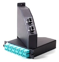
    12 Fibers, MTP to LC/SC/ST/FC, 50/125 10G OM3 Fiber, 12 Standard, LGX - MTP Cassette Panel

    Fiber-Mart’s MTP Cassette Modules provide secure transition between MTP and LC,SC,ST or FC discrete connectors with two types.
    The MTP modules are fitted with 12 or 24 fibers and have LC, SC adapters on the front side and MTP at the rear.
    Cassette Type: StandardCassette Type: Irregular shape
     
    The term MTP is a registered trademark of US Conec, it has been the main trend in European and American areas.
     

    Features

    • High performance zirconia sleeve adapters.
    • Rapid deployment Factory terminated modular system saves installation and reconfiguration time during moves, adds and changes.
    • MTP interface MTP components feature superior optical and mechanical properties.
    • Optimized performance Low loss MTP Elite, discrete Premium connectors and OM4 fiber assures low insertion losses and power penalties in tight power budget, high-speed network environments.
    • High density 12 or 24 fiber cassettes can be mounted in 1U scaling up to 72 or in 4U scaling up to 288 discrete connectors.
    • Reliability 100% tested - combination of high quality components and manufacturing quality control guarantees product to the highest standards.

    Application

    • Data centers
    • LAN, WAN and SAN
    • Interoffice cross-connects
    • Campus environments

    Mechanical Drawing:


    1U slide and tilt panel - holds up to 3 cassettes (72 fibers)MTP Cassette housing in 4U Rack mount

    MTP Cassette Structure

    MTP cable connect with MTP CassetteMTP Harness cable housing in MTP Cassette


    Specifications

    Connector requirements
      MultimodeSingle mode
    ILMTPSingle max:0.35dB(L)
    Single max:0.60dB(G)
    Single max:0.35dB(L)
    Single max:0.75dB(G)
    LCmax:0.10dB(L)
    max:0.15dB(G)
    MAX:0.3dB
    RLMTP>20dB>60dB(8°Angle Polish)
    LC>30dB>50dB(UPC)
    >60dB(APC)
    MechanicalMTP<0.2dB,200times insertion
    LC<0.2dB,200times insertion
    EnvironmentalWorking Temp.-20~ +60℃
    Storage Temp.-40~ +70℃
    Install Temp-5~ +50℃

    Order Information

    Order InformationPackaging
    Mode TypeFiber StandardFiber ConnectorFiber countsPolish Type1. MTP-FC/SC/ST/LC Fiber Optic Cable
    ( The type of fiber mode according to
    your choice MTP/MPO Cassettes )
    2. FC/SC/LC/ST Fiber Adapter
    3. MTP/MPO Fiber Adapter
    4. LGX box
    OM412 Fiber Standard
    24 Fiber Standard
    MTP-FC ( 12 fiber available )
    MTP-SC (12 fiber available )
    MTP-LC (12&24fiber available )
    MTP-ST (12 fiber available )
    12 Fibers
    24 Fibers
    UPC APC
    OM3
    OS1/2
    OM2
    OM1

    MPO/MTP Fiber Cables Data Center Applications

    by www.fiber-mart.com
    MPO/MTP Fiber Cable is offered for various applications for all networking and device needs like 100 Gig modules. It uses a high-density multi-fiber connector system built around precision molded MT ferrule. fiber-mart’s MPO fiber cables are available in UPC and APC finishes, support both multimode and single mode applications, and optional lengths available. Our MPO/MTP fiber cable is with push connector IEC 61754-7 and TIA/EIA 604-5A compliant and offer low cost per termination for high density applications. The MPO/MTP fiber cables are tested with guaranteed quality, and they can be installed easily, which saves time and money.
     
    MPO/MTP Standard Trunk Cables
     
    There are three types package MTP/MPO Cables: MPO/MTP Standard Trunk Cables, MPO/MTP Hybrid Trunk Cables, MPO/MTP Harnesses Cables and MPO/MTP Cassettes.
     
    MPO/MTP Standard Trunk Cables
     
    The MPO/MTP Trunk cable is designs for Data Center Applications. It is divided into round cable and flat cable with the outer diameter of 3.0 mm or 4.5 mm. The connector where this cable is terminated on is the so called MPO/MTP connector. All of MPO/MTP fiber optic patch cables are 100% optically tested for maximum performance. We have all lengths and connectors available.
     
    fiber-mart offer singlemode and multimode (OM1, OM2, 10G OM3, 10G OM4) MPO/MTP Cable. Singlemode MPO/MTP cable is primarily used for applications involving extensive distances, 10G MPO/MTP cable provide 10 gigabit data transfer speeds in high bandwidth applications and they are 5 times faster than standard 50um fiber cable. Work with both VCSEL laser and LED sources. The meanwhile, we also provide 40G/100G MPO/MTP trunk cable.
     
    MPO/MTP Hybrid Trunk Cables
     
    fiber-mart’s MPO / MTP Hybrid Trunk Cable are available in SM (9/125), MM (50 or 62.5/125), 10Gig fiber types. You could select the corning fiber according to your own needs with the selection of 12/24 fiber cores. The cable is MPO/MTP on one end, with single-fiber connectors on another end, single-fiber connector interface available in SC, ST, LC, MTRJ in forms of Simplex or Duplex channeling. The fiber splitters are available in both plastic and metal fiber splitter, which give you various selections.
     
    MPO/MTP Harnesses Cables
     
    fiber-mart’s MPO/MTP harnesses cables are usually divided into three types of MPO/MTP-MPO/MTP connector, MPO/MTP-Common connector, MPO/MTP-Secure Keyed LC connector and 40G/100G MPO/MTP
     
    Harnesses cable, according to different colors divided into SM, MM and 10G MM, you could select the corning fiber according to your own needs with the selection of 8/12/24 fibers.
     
    The MPO/MTP Harnesses cables differs from Trunk cables, it works from trunk backbone assemblies to fiber rack system, and the trunk cable is high density back bone cabling. The MPO/MTP harnesses cable application for data centers requiring quick infrastructure deployment with extended reach that want to maintain bandwidth throughout the infrastructure, it design cater for up-scaling needs and future technologies growth, it’s the best solution, which covers all fiber optic cabling needs in all areas of Data Center.
     
    MPO/MTP Cassettes
     
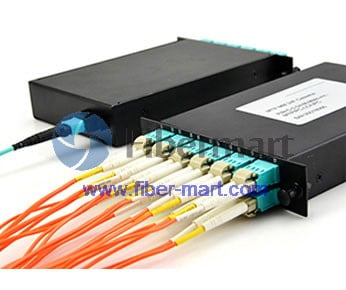
    MPO fiber optic cassette, with SC,LC,ST, FC connectors, is a highly flexible fiber management unit that can be used stand alone or integrated into the MPO fiber optic patch panels. fiber-mart supply high quality MPO cassette which is designed to reduce installation time and cost for an optical network infrastructure in the premises environment. We are direct manufacturer of the MPO fiber optic cassette, that also supply rack chassis like 1U 19” rack for putting more MPO LGX cassettes.

    How to Understand PoE and PoE+ Switches

    by www.fiber-mart.com Power-over-Ethernet (PoE) is the technology that allows network switches to transmit power and data through an Ethe...